-
Do you know what is a launch cable used for?
Categories: OTDRThe Optical Time Domain Reflectometer (OTDR) is a vital tool for fiber optic testing. However, there is an unwanted phenomenon known as ‘dead zone’ that occurs when using an OTDR. This dead zone limitation can be avoided through the use of an OTDR Launch Box. OTDR Launch Cables are designed to be used in conjunction with an OTDR to measure complete link loss of a fiber.
The Launch Box Basics
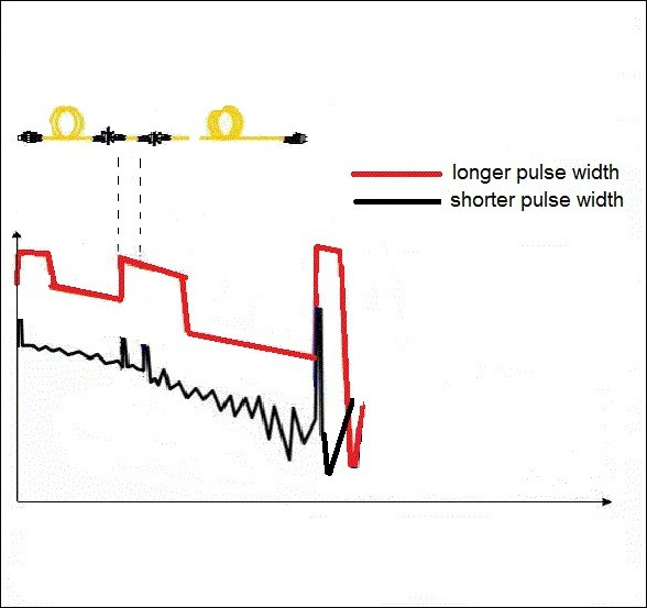
The launch box, which is also known in the industry as a launch fiber, pulse suppressor, dead zone box or fiber ring, is a device that helps to eliminate the dead zone issue during fiber optic testing significantly. The dead zone is something that occurs when the pulse width changes and causes a high degree of reflection that can cover an area several hundred meters from where the OTDR is located. This results in the OTDR device not being able to detect events or issues in that area. Launch cables are offered in a variety of connector styles including SC, ST, LC, FC. -
Do You Need OTDR Dead Zone Eliminator Launch Box?
Categories: OTDROptical Time Domain Reflectometry (OTDR) is an essential fiber testing tool. It can test optical losses and locate breaks, connectors and connectors in fiber optic networks. However, OTDRs have a “dead zone” and may affect test results if appropriate measures are not taken. To overcome the limitations of the OTDR dead zone, OTDR launch boxes are being used. This article will introduce the OTDR launch box for your reference.

Basic of OTDR Launch Box
The OTDR launch box has many other names, such as dead zone boxes, pulse suppressors, fiber optic rings, fiber optic launch cables, etc.
The dead zone of the OTDR is caused by high reflection levels and is affected by the pulse width and may extend hundreds of meters from the OTDR. It is recommended to use a full-length fiber before the fiber under test. Therefore, the OTDR receiver ca -
Experience and skills in operating OTDR
Categories: OTDR1. Use of OTDR
Fiber optic measurements with OTDR can be divided into three steps: parameter setting, data acquisition, and curve analysis.
Manually setting measurement parameters includes:
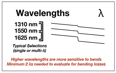
(1) Wavelength selection (λ):
Because different wavelengths correspond to different light characteristics (including attenuation, microbend, etc.), the test wavelength generally follows the principle corresponding to the transmission wavelength of the system transmission, that is, when the system is open at 1550 wavelength, the test wavelength is 1550 nm.
(2) Pulse Width:


The longer the pulse width, the larger the dynamic measurement range and the lo


