Problem
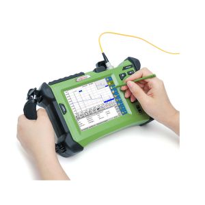
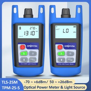
An optical fiber cable run has been installed between two buildings, with a splice point in the middle linking a third building. It is now time to certify the link with a light source and power meter. The test equipment is set up to test at 850 nanometers. The source is connected to fiber 1 at the main crossconnect and the power meter at the intermediate crossconnect. The loss measured for this fiber span is 4.0 decibels. Is this attenuation acceptable?
At theFo, We are frequently asked how much loss you are allowed when conducting testing on fibre optic cabling. Unfortunately, it’s not a simple answer and depends on different factors. So how do you determine acceptable loss?
Firstly, it depends on who is doing the testing and in what phase of a project the cabling is being tested. For instance, contractors are often paid to install, terminate and certify the cabling but have no idea what their client plans to run on the cabling. So, unless the client’s plans have specifications for acceptable attenuation (insertion loss), the installer should determine the correct value based on the specifics of each link being tested.
If the installer knows what the client plans to run on the system, they can refer to the standards for that application to determine acceptable loss. Also, if the make and model of the network equipment is known, installers can look to the specification for loss limits based on specific applications (typically a variation of Ethernet), and loss budget calculations, based on the actual networking equipment that will be operating on the installed cabling.
Cabling based loss budgets
This is a popular method for determining the acceptable loss for certification of the cabling following installation. Using an optical power meter and light source or OLTS (Optical Loss Test Set), Tier 1 Certification can be performed against industry standard limits for cable and connectors. Both the TIA and ISO cabling standards list the acceptable loss limits for fibre optic components and these values can be used to calculate a loss budget.
The TIA-568.3-D (2016) standard lists the following transmission performance parameters for optical fibre:
|
Optical fibre type |
Wavelength (nm) |
Maximum attenuation (dB/km) |
Minimum overfilled modal bandwidth-length product (MHz-km) |
Minimum effective modal bandwidth-length product (MHz-km) |
|
850nm laser optimised, 50/125 μm Multimode, (OM3) |
850 1300 |
3.0 1.5 |
1500 500 |
2000 Not required |
|
850nm laser optimised, 50/125 μm Multimode, (OM4) |
850 1300 |
3.0 1.5 |
3500 500 |
4700 Not required |
|
Single-mode indoor/outdoor |
1310 1383 1550 |
0.5 0.5 0.5 |
N/A N/A N/A |
N/A N/A N/A |
|
Single-mode inside plant |
1310 1383 1550 |
1.0 1.0 1.0 |
N/A N/A N/A |
N/A N/A N/A |
|
Single-mode outside plant |
1310 1383 1550 |
0.4 0.4 0.4 |
N/A N/A N/A |
N/A N/A N/A |
|
Connectors/splices |
|
Maximum attenuation |
|
|
|
Standard grade connector pair |
|
0.75 dB |
|
|
|
Reference-to-Standard grade connector pair |
|
0.50 dB |
|
|
|
Splice (fusion/mechanical) |
|
0.30 dB |
|
|
To make the process easier, some testers like the LanTEK IV-S with FiberTEK IV-S modules from THEFO Networks have built-in loss budget calculators so you can enter the variables and automatically determine the loss limit. Take an example of a simple 90-metre horizontal multimode cable link with a patch panel at one side and a work area outlet at the other.

|
Multimode Loss Budget |
850nm |
1300nm |
|
Cable Length 90m |
0.09km |
0.09km |
|
Cable Attenuation Coefficient |
3.0dB/km |
1.5dB/km |
|
Cable Loss (length x attenuation) |
0.03dB |
0.01dB |
|
# Connector pairs |
2 |
2 |
|
Connector Insertion Loss (IL) Reference-to-Standard grade |
0.5dB |
0.50dB |
|
Connector Loss (# connectors x IL) |
1.0dB |
1.00dB |
|
# Splices |
0 |
0 |
|
Splice IL |
0.30dB |
0.30dB |
|
Splice Loss (# splices x IL) |
0dB |
0dB |
|
Total Link Budget |
1.03dB |
1.01dB |
Using the same concept, lets calculate the budget for a 1,500-metre multimode link with 2 splices and a connection at each end.


|
Multimode Loss Budget |
850nm |
1300nm |
|
Cable Length 1500m |
1.50km |
1.50km |
|
Cable Attenuation Coefficient |
3.0dB/km |
1.5dB/km |
|
Cable Loss (length x attenuation) |
4.50dB |
2.25dB |
|
# Connector pairs |
2 |
2 |
|
Connector Insertion Loss (IL) Reference-to-Standard grade |
0.5dB |
0.50dB |
|
Connector Loss (# connectors x IL) |
1.0dB |
1.00dB |
|
# Splices |
2 |
2 |
|
Splice IL |
0.30dB |
0.30dB |
|
Splice Loss (# splices x IL) |
0.60dB |
0.60dB |
|
Total Link Budget |
6.10dB |
3.85dB |
The previous calculations tell the installer what the pass/fail limit in the tester needs to be set to in order to certify each of the links to TIA/ISO cabling standards. In this case the measured insertion loss needs to be less than 6.10dB at 850nm and 3.85dB at 1300nm for the link to pass.
Keep in mind that this calculation is for the cabling only. It does not take into account the communication application that will be running over the link. Some applications in the table below will not operate over this link because it exceeds both the length and insertion loss allowances.
For example, 10GBase-LX4 (10G Ethernet at 1300nm) allows a maximum loss of 2.0dB and a maximum distance of 300 metres (yellow highlight). A 1,500-metre link with up to 3.85dB of insertion loss exceeds both the insertion loss and length limits of 10GBase-LX4.
100Base-FX (100Mb Ethernet at 1300nm) highlighted in green allows a maximum insertion loss of 6.0dB and a maximum length of 2,000 metres. The example link will support 100Mb Ethernet if the test passes the limits determined by the loss budget calculation.
Using application specific limits
It’s easiest to determine a loss budget when the application that the fibre will support is known as you can look up the requirements for each application.
Below is an excerpt from the TIA-568.0-D standard that lists requirements for a few common Ethernet applications.
|
Multimode Ethernet Applications |
Fibre Type |
62.5/125 μm |
50/125 μm |
850 nm laser-optimized 50/125 μm |
|||||
|
Fibre Standard |
TIA 492AAAA (OM1) |
TIA 492AAAB (OM2) |
TIA 492AAAC (OM3) |
TIA 492AAAD (OM4) |
|||||
|
|
Nominal wavelength (nm) |
850 |
1300 |
850 |
1300 |
850 |
1300 |
850 |
1300 |
|
Application |
Parameter |
|
|
|
|
|
|
|
|
|
Ethernet 10/100BASE-SX |
Channel attenuation (dB) |
4.0 |
– |
4.0 |
– |
4.0 |
– |
4.0 |
– |
|
Supportable distance m (ft) |
300 |
– |
300 |
– |
300 |
– |
300 |
– |
|
|
Ethernet 100BASE-FX |
Channel attenuation (dB) |
– |
11.0 |
– |
6.0 |
– |
6.0 |
– |
6.0 |
|
Supportable distance m (ft) |
– |
2000 |
– |
2000 |
– |
2000 |
– |
2000 |
|
|
Ethernet 1000BASE-SX |
Channel attenuation (dB) |
2.6 |
– |
3.6 |
– |
– |
– |
– |
– |
|
Supportable distance m (ft) |
275 |
– |
550 |
– |
Note 1 |
– |
Note 1 |
– |
|
|
Ethernet 1000BASE-LX |
Channel attenuation (dB) |
– |
2.3 |
– |
2.3 |
– |
2.3 |
– |
2.3 |
|
Supportable distance m (ft) |
– |
550 |
– |
550 |
– |
550 |
– |
550 |
|
|
Ethernet 10GBASE-S |
Channel attenuation (dB) |
2.4 |
– |
2.3 |
– |
2.6 |
– |
2.9 |
– |
|
Supportable distance m (ft) |
33 |
– |
82 |
– |
300 |
– |
400 |
– |
|
|
Ethernet 10GBASE-LX4 |
Channel attenuation (dB) |
– |
2.5 |
– |
2.0 |
– |
2.0 |
– |
2.0 |
|
Supportable distance m (ft) |
– |
300 |
– |
300 |
– |
300 |
– |
300 |
|
|
Ethernet 10GBASE-LRM |
Channel attenuation (dB) |
– |
1.9 |
– |
1.9 |
– |
1.9 |
– |
1.9 |
|
Supportable distance m (ft) |
– |
220 |
– |
220 |
– |
220 |
– |
220 |
|
|
Ethernet 40GBASE-SR4 |
Channel attenuation (dB) |
– |
– |
– |
– |
1.9 |
– |
1.5 2 |
– |
|
Supportable distance m (ft) |
– |
– |
– |
– |
100 |
– |
150 |
– |
|
|
Ethernet 100GBASE-SR4 |
Channel attenuation (dB) |
– |
– |
– |
– |
1.9 |
– |
1.9 |
|
|
Supportable distance m (ft) |
– |
– |
– |
– |
70 |
– |
100 |
|
|
|
Ethernet 100GBASE-SR10 |
Channel attenuation (dB) |
– |
– |
– |
– |
1.9 |
– |
1.5 2 |
– |
|
Supportable distance m (ft) |
– |
– |
– |
– |
100 |
– |
150 |
– |
|
These charts make easy work of determining loss budgets as long as the application that will be running over the fibre is known. Plus, some fibre certifiers incorporate a database with these values, so you can simply choose the appropriate standard, and the pass/fail limits are set automatically.
Calculating loss budgets for networking equipment
When the networking equipment that will be running over the fibre is known, the requirements of that can be used to determine the loss budget. Each piece of optical networking equipment, even SFP/GBIC modules will have specifications for output power and receiver sensitivity. These tell the user exactly how much loss the equipment can sustain and still operate properly.
Transmitter output specifies how “bright” the light is that is emitted from the transmitter port. The specification will be in dBm (not dB). A typical device may have an output power of -20dBm. Don’t let the negative confuse you, it doesn’t mean negative power. 0dBm is a reference to 1mW (milliwatt) of power, and a negative dBm value simply means less than 1mW.
Note: dBm is an amount of power. dB is a change in power from one level to another.
A receiver usually has two specifications, Receiver Sensitivity and Dynamic Range.
Receiver Sensitivity is the weakest (darkest) signal the receiver can detect and the Dynamic Range is how much brighter than the Sensitivity specification the light can be without blinding the receiver. For example, a receiver with a Sensitivity of -30dBm and a Dynamic Range of 20dB can detect light within a range of -10 to -30dBm.
If the transmitter injects light into the fibre at -20dBm, and the weakest light the receiver can detect is -30dBm, the difference between the two is 10dB. Meaning that the system can have at most 10dB of loss before the signal is too weak for the receiver to detect.
What if the receiver was paired with a transmitter that output -5dBm of power? The signal would be too strong and overpower the receiver. With optical systems, care must be taken to not overdrive receivers because it will be just as detrimental as having too little signal.
For more information on determining acceptable loss and testers for fibre optic cabling, visit https://www.thefo.com/ contact via whatsapp/ skype +86 13625297051 or mail our mail box sales@thefo.com


